Advanced Topic Skip if you’re new, explore when you’re ready.
Stepper motors are created much the same way as servos are:
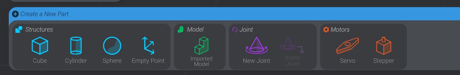
Click or drag out a stepper motor to create one:
Bottango currently supports three kinds of connections to stepper motors:
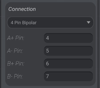
In this connection type, you supply four pins: two pins for the A coil, and two pins for the B coil of your bipolar stepper motor.
Here’s an example of the kind of controller you would use for this connection type: The Adafruit DRV8833 DC/Stepper Motor Driver Breakout Board.
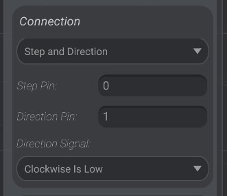
In this connection type, you supply two pins.
The first is the step pin. This is the pin that will signal to the breakout board to step on a rising edge on that pin.
The second pin is the direction pin. This indicates to the breakout board if the step should be clockwise or counterclockwise. You can set whether a low signal on that pin should mean a clockwise or counterclockwise step. The setting here will depend on your exact board as well as the order you wired up the coils of your stepper motor. You may need to experiment with both settings.
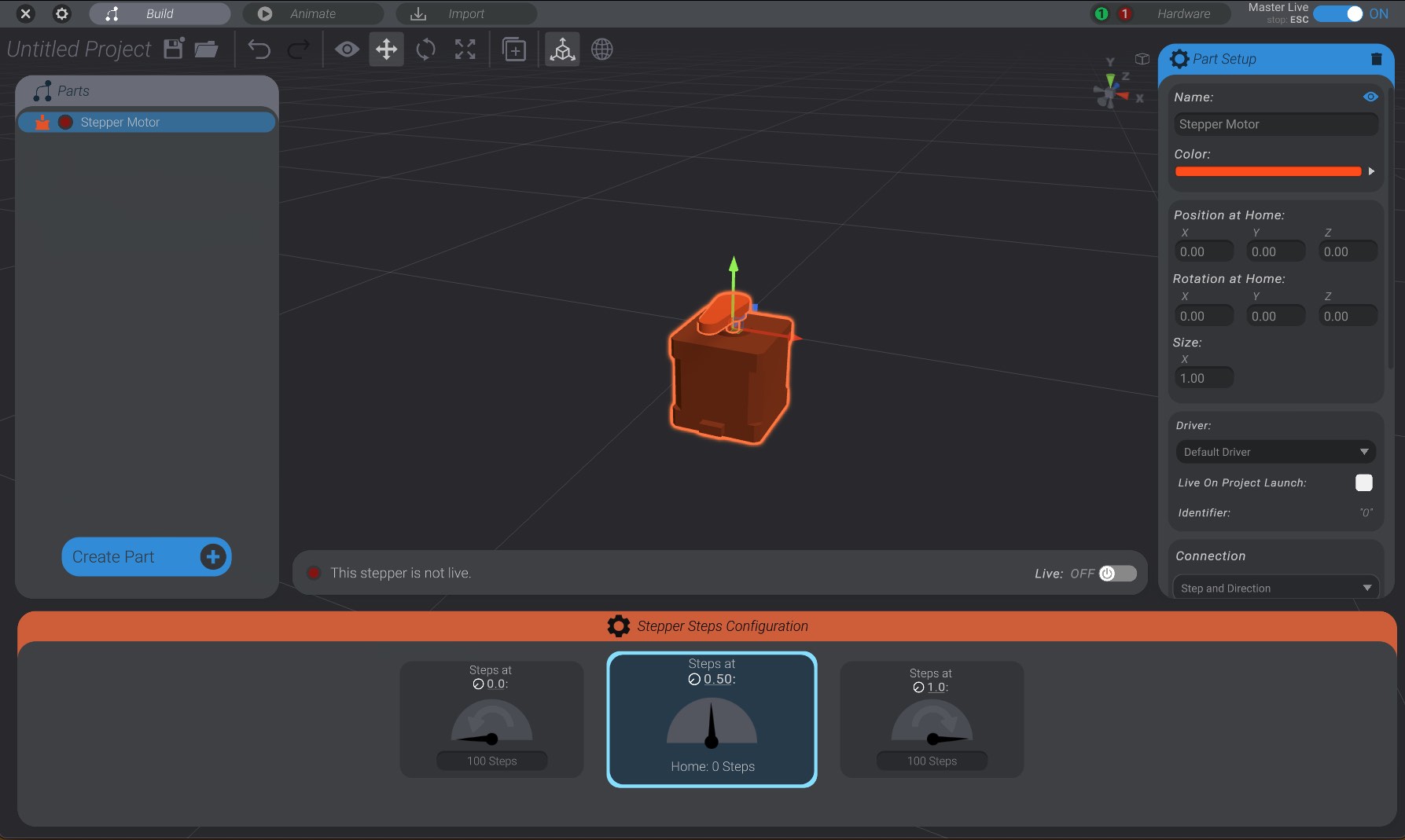
You configure the steps values of a stepper motor in much the same way you configure the PWM of a servo motor:
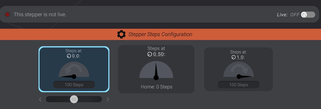
On the right you enter the number of clockwise steps the stepper should take to move to its maximum movement (![]() 1.0).
1.0).
On the left you enter the number of counterclockwise steps the stepper should take to move to its minimum movement (![]() 0.0). Note that this is always a negative number. You move positive steps from home clockwise, and negative steps from home counterclockwise. You can use the nudge slider to nudge the values as well.
0.0). Note that this is always a negative number. You move positive steps from home clockwise, and negative steps from home counterclockwise. You can use the nudge slider to nudge the values as well.
Finally, unlike a servo, a stepper’s “home” is always 0 steps. This is the state the stepper motor should be in when it is synchronized, as we’ll discuss in Synchronizing Stepper Motors.