Essential Topic for learning Bottango.
You set a servo to its real-world desired rotation by having the hardware driver send a PWM signal in a range between the minimum and maximum possible PWM values. Most servos have a different hardware-bound absolute max and min range of acceptable PWM values, and in your robot, usually there’s a smaller subset of that range that you want the robot to actually use.
When you are configuring your motor, you should not use the absolute maximum hardware range that the servo could accept as the PWM values. Instead use the smaller range of minimum and maximum PWM values you want the robot to actually use when animating it.
Shown here are the default PWM configuration values for a servo.
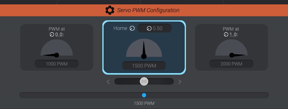
This servo will express 1000 PWM at its furthest in one rotation direction, and 2000 PWM at its furthest in the other direction.
Click the left-hand option to set the minimum signal value, the right-hand side to set the maximum signal value, and the middle option to select the “home” signal value.
You can enter in the desired values as text directly in the text fields. Any changes in the servo configuration will be reflected in your real-world servo if it is connected and enabled. Or, if you want to tweak your values, you can use the “slider” below the selected option. Pushing the slider to the left will nudge the value lower, and to the right will nudge the value higher. The further left or right, the faster the value changes.
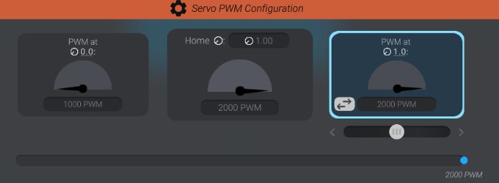
With the minimum signal or maximum signal value option selected, you’ll also be shown a button next to the text input field to invert the min and max signal if you’d like. In the example shown, pressing the button will switch from 1000 -> 1500 -> 2000 as the range of signal to 2000 -> 1500 -> 1000.
Just like when creating joint offsets, you’ll see a movement icon ![]() . This icon is used to stand in for a unified concept throughout Bottango called “Movement.” A longer name for it could be called “normalized range of movement.”
. This icon is used to stand in for a unified concept throughout Bottango called “Movement.” A longer name for it could be called “normalized range of movement.”
If you haven’t already read Joint Offsets, be sure to read that now. Movement stands for the value of an object between its minimum value and maximum value, on a 0.0 to 1.0 scale. Just like how joints use movement to represent the min and max position or rotation a joint can be in, motors use movement to represent the minimum and maximum signal that can be safely expressed while animating the motor.
Using movement rather than direct values allows us to have a single unifying number to keep multiple concepts in sync. For example, when we create a joint, we’ll be defining the minimum and maximum position or rotation offsets from home for that joint. Those minimums and maximum offsets will map directly to the minimum and maximum PWM values defined here on the motor. This allows us to make changes to one part of the project, and since we’re using movement (normalized values), the rest of the project will stay in sync.
In this context, you are setting what PWM value the motor should be at when at minimum movement (![]() 0.0) and what PWM value the motor should be at when at maximum movement (
0.0) and what PWM value the motor should be at when at maximum movement (![]() 1.0).
1.0).
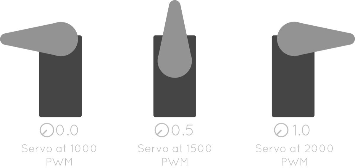
Here you can see how the currently configured PWM values of this motor map to what you would see on a real-life servo, and the associated movement values:
It’s okay if movement doesn’t make total sense yet. As you spend more time with Bottango, it will start to sink in.
The middle PWM value to configure on the servo is the home PWM value. This is the value that the servo will be in “at rest.” If you think back to when we created structure, we did so in its home position and rotation. When Bottango moves and rotates joints, it offsets the joint away from its home position and rotation, and then returns back to that home position and rotation when at rest. Bottango will do the same thing with motors, move them to the desired PWM value, and then return them to rest at their home PWM value.
You can see that in this example, the home PWM value is set to 1500. Because that is exactly halfway between the minimum value of 1000 and the maximum value of 2000, it results in a home movement value of ![]() 0.5 (halfway between
0.5 (halfway between ![]() 0.0 and
0.0 and ![]() 1.0). If you prefer to think of your configuration via movement, you could also type in the movement value and let Bottango calculate the actual PWM value. For example, you could set the home movement value to
1.0). If you prefer to think of your configuration via movement, you could also type in the movement value and let Bottango calculate the actual PWM value. For example, you could set the home movement value to ![]() 1.0, and your home PWM will be whatever your maximum PWM value is.
1.0, and your home PWM will be whatever your maximum PWM value is.
Once a motor and a joint are linked, ideally they both have the same home movement, so that sending your robot home sends both the motor and the joint to the same home. If they are not the same, Bottango provides tools to help deal with that in Resolving Home Conflicts.
Let’s say we linked a servo to the BaseExtension joint, associated it with the default driver in the project, and set its pin to pin 5.
You can see that the joint is set up to rotate -45 degrees from home at the minimum movement (![]() 0.0) and
0.0) and +45 degrees from home at the maximum movement (![]() 1.0).
1.0).
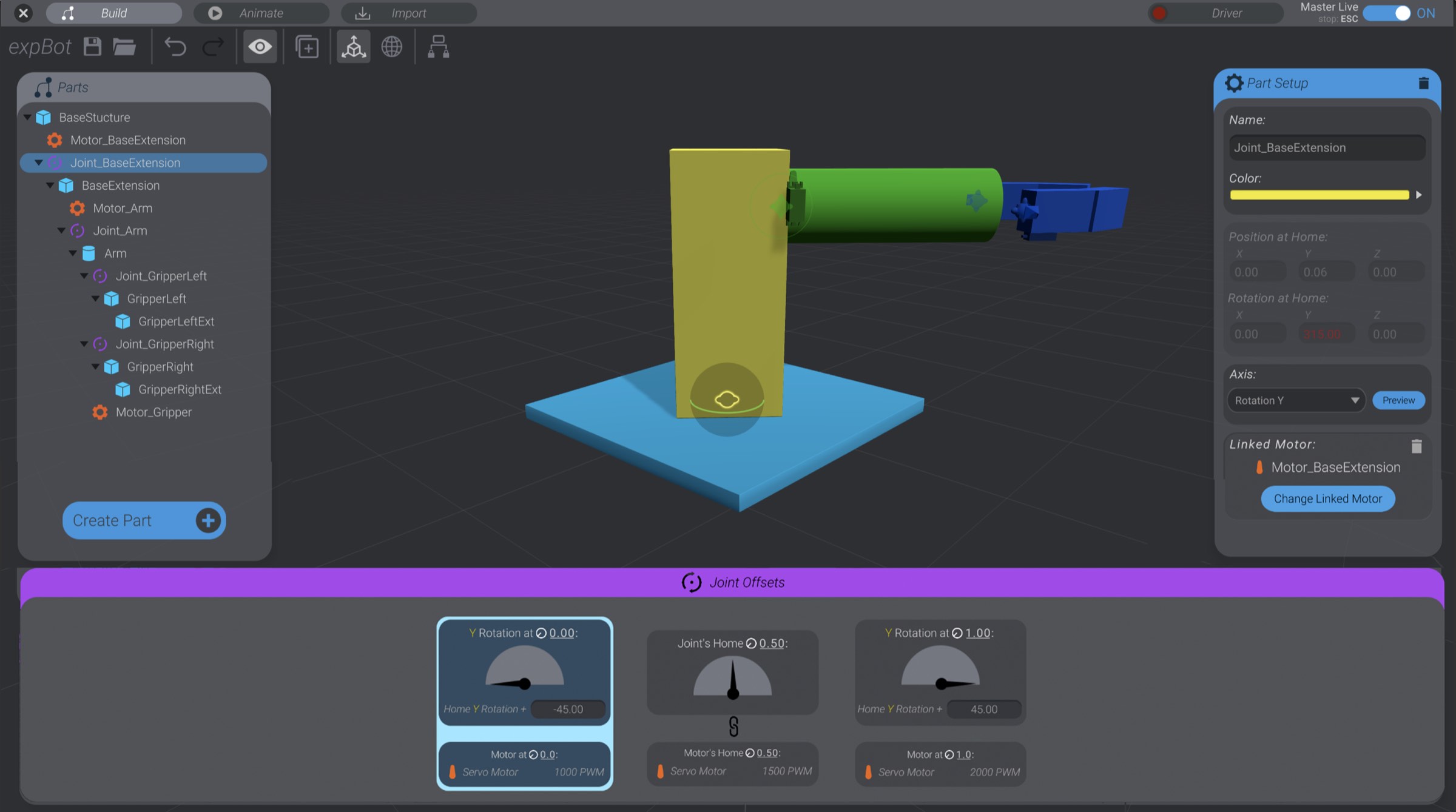
If we link the servo to the BaseExtension joint and leave it at its default settings:
When the joint is animated all the way in negative rotation from home direction (![]() 0.0), the servo will express
0.0), the servo will express 1000 PWM.
When the joint is animated all the way in positive rotation from home direction (![]() 1.0), the servo will express
1.0), the servo will express 2000 PWM.
When the joint is driven to its neutral home (![]() 0.5), the servo will express
0.5), the servo will express 1500 PWM.
As the joint animates between the min and max movement values, the mapping between joint angles and servo PWM will be handled automatically for you.
If you’d like, you can experiment and finish setting up the signal range for all the servos in this example project. This is the last time we’ll use this example robot in this documentation, though.