Essential Topic for learning Bottango.
When you select a motor, on the right side of the screen will be configuration options, just as with joints and structures.
Every motor needs an associated hardware driver. Since we haven’t yet covered hardware drivers, they are digital representations of the microcontroller that your motor is connected to. An example hardware driver would be an Arduino Uno R3 running Bottango firmware and connected to your computer. When you create a project, a default hardware driver is created for you in the project. We’ll cover setting up and connecting to the hardware driver in the hardware drivers section.
The hardware driver you associate with a motor is the hardware driver that will receive all commands from Bottango when the motor is moved.
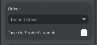
All created hardware drivers in the Hardware view will be listed as options in the driver dropdown menu on the Motor Configuration panel.
If you associate a motor with a hardware driver, then later delete that hardware driver, the motor will associate with the default hardware driver as the replacement.
Additionally, just like a hardware driver, a motor can be live or not live on program launch.
Your hardware driver has a particular way it is connected to your motor, and Bottango needs to know it in order to successfully communicate with your hardware driver. As a basic example, a servo is driven on a hardware driver via PWM output from a digital pin on the microcontroller.
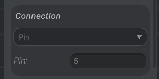
Here you can see this servo has been configured on the driver to be driven via a pin, and the pin is set to 5.
Only one motor can have the same connection configuration. For example, if two motors are both associated with the same driver, and have the same pin, one of them will be set to not live, and cannot be reenabled until the conflict is resolved. You will see this if you create two motors in a row without changing their connection and driver configuration, as both motors will have the default driver and default connection.
You can set a servo to connect via a pin, or use the drop-down to change it to be driven over I2C. This is useful if you are using the Adafruit 16 channel PWM driver.
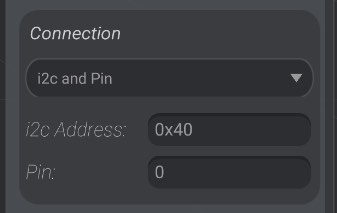
You will need to enter the I2C address in hexadecimal or integer format, as well as the pin for the servo.
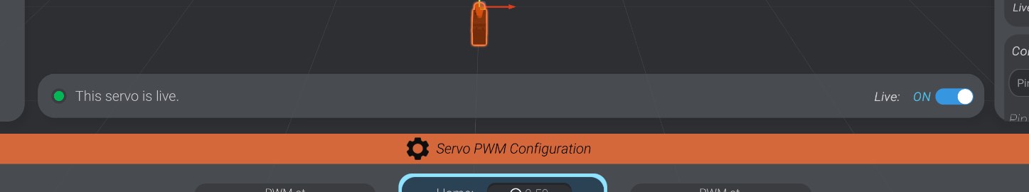
Near the bottom of the screen, you’ll see an indication of the status of the motor, and whether the servo is live or not live.
When a motor is live, and its driver is live and connected as well, Bottango will be actively trying to mirror the simulation to your motor in real life one-to-one. When the motor is not live, the motor is not driven by Bottango. You’ll see a green status indicator for live, and red for not live.
You can change the live state of the motor here and in the hardware status view.
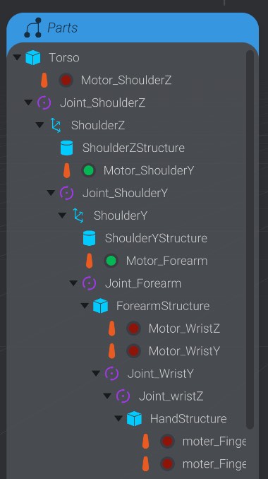
Finally, you can see the same status indicator next to each motor in the parts list:
A newly created motor is not live by default. You must turn the motor to live once you have finished configuring it to begin driving that motor.
When you’re moving a motor between positions, you often don’t want it to go as fast as mechanically possible to its new destination. Max speed limits the speed with which a motor will transition from one value to another so as to not damage your robot.
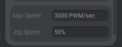
The hardware driver will attempt to not allow the motor to exceed the max speed you have entered here, even if you animate it faster than the limit set. As well, when you are animating your robot, you’ll see warnings when an animation moves faster than the given max speed. We’ll talk about that more in Graph View.
Finally, you’ll see a field to set the “jog speed” of a motor. This is the speed that Bottango moves the motor and associated joints when moved for any reason other than playing an animation. Jog speed is a percentage of the max speed of the motor. As an example, a servo defaults to 50% jog speed, which means if the maximum speed is 3000 PWM/sec, the jog speed will be 1500 PWM/sec.
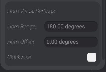
As your motor moves, as a helpful visual guide the horn moves as well. For each kind of motor, there is a default range of rotation, however, you can adjust that rotation however you’d like using the horn visual settings: