Essential Topic for learning Bottango.
A joint articulates by moving or rotating away from its home position or rotation. When a joint is selected, you can configure the range of allowed offsets from home.
Let’s start with a simple example. Here I have created a side project with a motor, a cube structure, and a joint that moves back and forth in the X-axis:
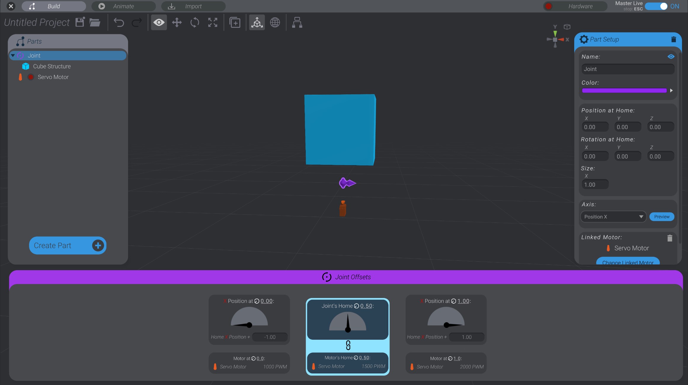
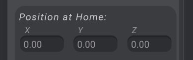
Here you can see that the cube is a child of the joint. As the joint moves in the X-axis, so too will the cube. The joint has a “home position” of 0.0 in the X dimension (as well as Y and Z).
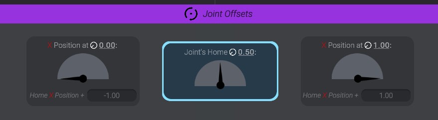
When I select a joint, I’ll be shown the “Joint Offsets” panel at the bottom of the screen.
Throughout the UI in Bottango, you’ll see an icon that looks like this: ![]() .
.
This icon is used to stand in for a unified concept throughout Bottango called “Movement.” A longer name for it could be called “normalized range of movement.”
Movement is expressed as a value between 0 and 1, and it represents the movement of a joint or motor within its possible range of movement. If you see ![]() 0.0, that means the part is at the minimum side of its range of movement. If you see
0.0, that means the part is at the minimum side of its range of movement. If you see ![]() 1.0, that means the part is at the opposite maximum side of its range of movement.
1.0, that means the part is at the opposite maximum side of its range of movement.
In this simple cube example, ![]() 0.0 movement is the joint (and child cube) moved as far left as it can go, and
0.0 movement is the joint (and child cube) moved as far left as it can go, and ![]() 1.0 movement is the joint moved as far in the opposite direction to the right as it can go.
1.0 movement is the joint moved as far in the opposite direction to the right as it can go.
Later, this same concept will be used as the glue between how the range of possible motion on a motor relates to the range of motion on a joint. It’s such a foundational piece of Bottango, it’s even where the icon of the app comes from! But if you don’t quite get it yet, that’s okay; keep reading!
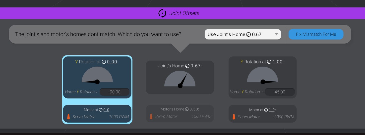
Now when I click on the left offset cell (offset at minimum movement ![]() 0.0), I will move the joint to its minimum position:
0.0), I will move the joint to its minimum position:
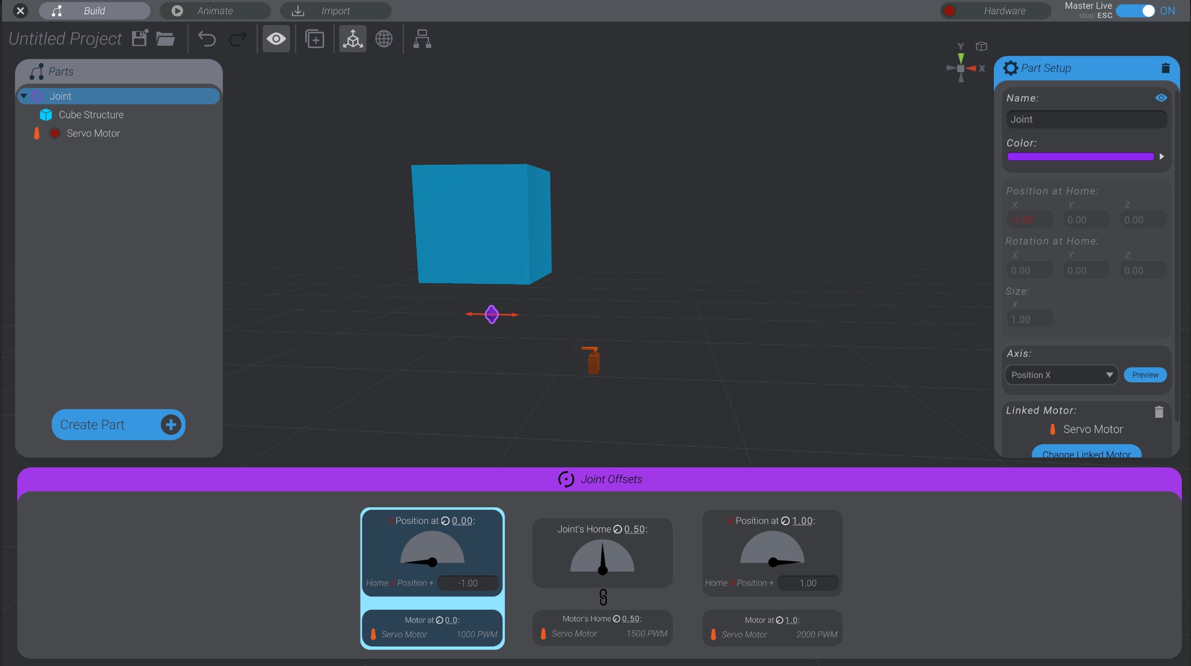
The joint moved to a position -1.0 in the X-axis. You can see this by the movement of the joint, and also by seeing how its position field now says “-1.0.” You’ll also notice the X position field is red. Any time a joint is offset from its home position or rotation, the offset axes are shown in red.
Why -1.0? Well, home is 0.0 in the X, and the offset at minimum value is set to -1.0. So that means that when the joint is at minimum, it will move -1.0 units from its home value (0.0) in the axis set (X position).
If I change the offset value to -0.5 instead, the joint moves -0.5 from home.

I can also click to select the offset at maximum movement (![]() 1.0), and configure and visualize that value as well:
1.0), and configure and visualize that value as well:
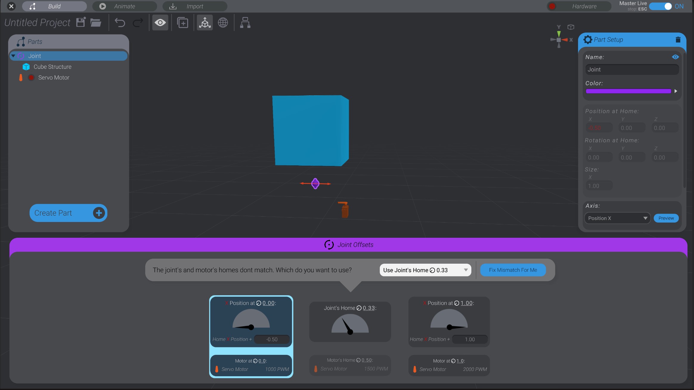
You’ll notice as you change the minimum and maximum offsets, that you’ll sometimes get a warning that the joint’s home value and the motor’s home value no longer match. This is because as you’re changing your joint’s offsets, you’re also changing what home is for that joint. We’ll talk later about what to do about that. For now, it’s ok to ignore that warning.
Select the joint that is the parent of BaseExtension if it is not already selected.
Click “Offset at Minimum” to set the minimum offset for this joint.
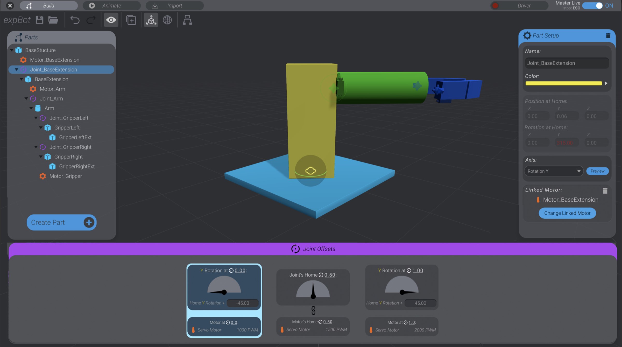
The joint currently has the default value of -45 degrees.
Change the value to -90 degrees.
Select the maximum offset, and change that value from +45 degrees to +90 degrees.
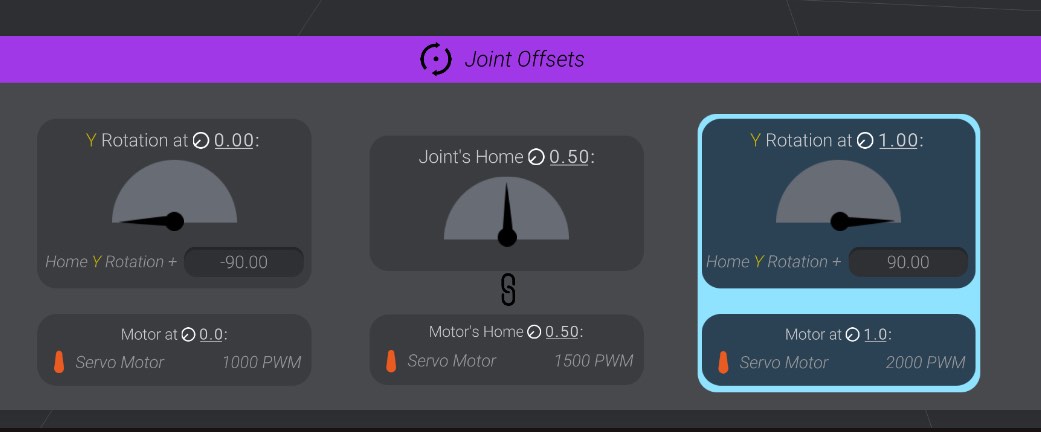
We’ve set the joint to sweep 180 degrees total (from -90 degrees to +90 degrees), with home in the center (![]() 0.5).
0.5).
As you click either extreme side of the offsets, you’ll see that the base extension rotates within the bounds we’ve set. Repeat these steps on the other joints in the project. When you get to the gripper, you’ll be setting how far it can move instead of how far it can rotate, but the concept is the same. The size of position movement values are usually much smaller than rotation degrees.
Save this project. We’ll come back to it when we add motors to learn how to link the movement of a joint to commands on your real-world motors, effectors, and hardware.