Attach Servos To Joints
Now that we’re connected to hardware, and have modeled out the 3D simulation of our robot, we need to link the movement of the 3D simulation with real-world movement on servos.
As mentioned earlier, we’ll be using the simplest hardware for a project in Bottango:
- 1x Arduino Uno R3 connected to the computer via USB
- 2x PWM Servo Motors
- 1x Bottango Servo Shield to power the servos.
Set Up the Forearm Servo
Section titled “Set Up the Forearm Servo”-
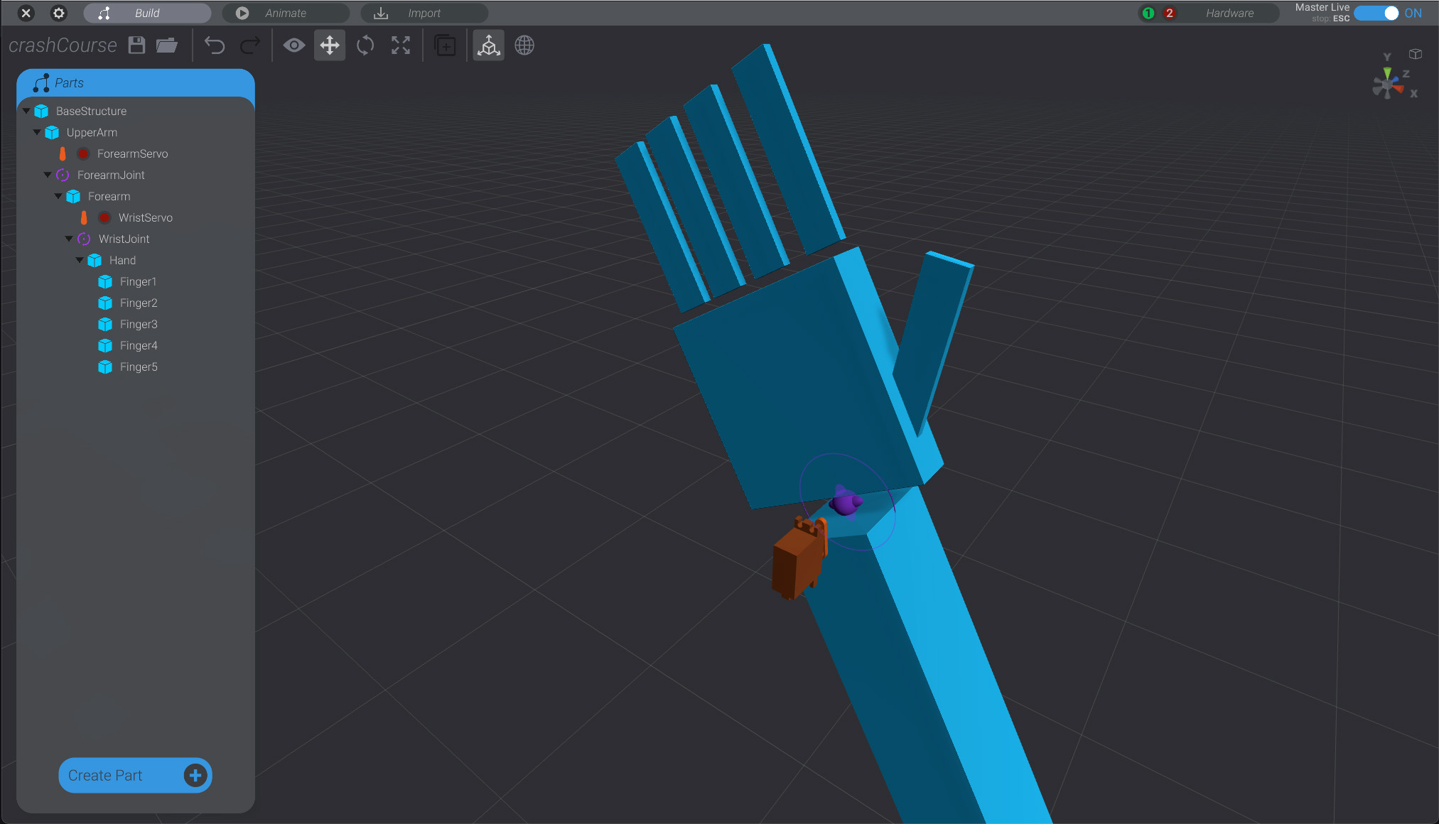
Go back to the Build view in your project, and with no parts selected, click the “
Create Part” button, and create a new servo in the project.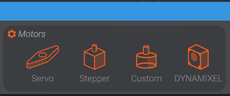
-
Name the created servo “
ForearmServo”, make it a child ofUpperArm, and move it about to where it would be in a real robot to articulate theForearmJoint. Correct parenting and positioning of the servo in the 3D simulation is not strictly required to simulate and drive your robot, but it’s often helpful for project organization.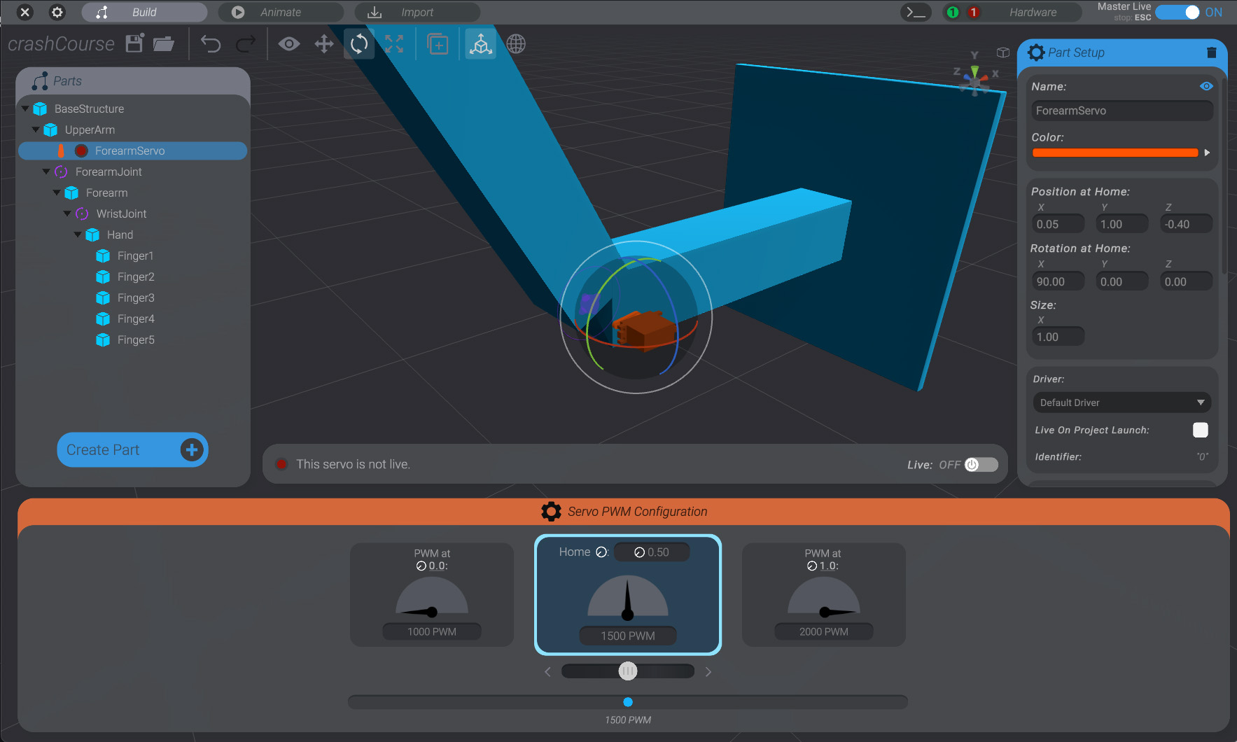
-
On the right side of the screen, in the “
Connection” sub-menu, you input the desired GPIO pin on your hardware to control this servo. Because we’re using an Arduino Uno R3, and a Bottango Servo Shield, the connection is simple. The servo is plugged into the header labeled “5” so we choose pin5.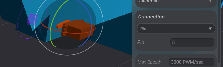
-
In order to turn the servo “on” we need to set it to “
Live.” Use the bottom “Servo Live” menu:
and set the servo to “
Live.”
-
With the default servo settings, the servo will animate between two PWM values:
1000 PWM-2000 PWM, and with1500 PWMas the home position. We likely want to adjust these values for our robot.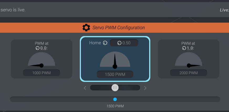
-
When you select each side of the range of signal for the servo, you’ll be able to adjust the allowed signal range in that direction. As well, if you’re connected to hardware and have set up things correctly, your real-world servo will move to the signal you’ve input.
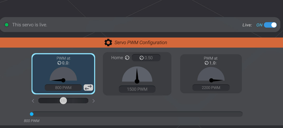
In this case, values closer to
800 PWM-2200 PWM(while maintaining a1500 PWMhome) feel appropriate. -
We need to now link the ForearmJoint to this servo. Click
ForearmJointto select it. On the right side of the screen, with the joint now selected, you’ll see a “Linked Motor” submenu.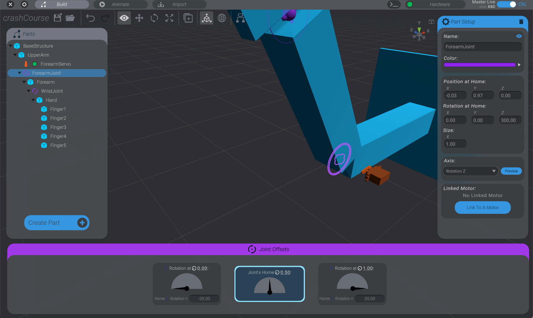
-
Click on the “
Link To A Motor” button, and then click on theForearmServopart we just created. This will link the movement ofForearmJointto real-world movement onForearmServo.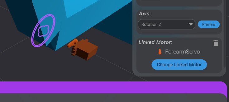
Now, with ForearmJoint selected, try again clicking between the range of movement of ForearmJoint.
You’ll see that both the 3D simulation and the real-world motor move. However, they may not be perfect mirrors of each other. You’ll need to tweak and adjust the settings of both the joint range of movement and the servo range of signal until you have:
- Signal values on the Servo that travel your full desired real-world movement
- Range of rotation on the joint that matches the 3D simulation to the real-world servo movement
- The same direction of rotation between the simulation and the real-world servo. If you find that they’re inverted from each other, it may be easier to flip the range of rotation on the joint than to flip the range of signal on the servo.
Create WristServo
Section titled “Create WristServo”Repeat the process, creating a servo named “WristServo.” The steps for this servo will match the ones above.
- Make
WristServoa child ofForearm - Place
WristServoin the correct position - Set
WristServoto pin6 - Link
WristJointtoWristServousing the “Linked Motor” submenu withWristJointselected.